Phasor resistive systems Transformer with resistance and leakage reactance Generalize impedance to expand ohm’s law to capacitors and inductors
Phasor Diagram of Synchronous Generator or Alternator
Resistive purely phasor Btech first year notes: ac circuit-single phase & 3 phase, basic Phasor diagram of synchronous generator or alternator
Diagram phasor load resistive power systems electric fig
Phasor diagram with resistive loadPhasor capacitive Basic source/load relationshipsWhat is power factor?.
Lagging law capacitors impedance ohm inductors phasor current leading load power negative form dummies complex generalize expand voltage inductive factorPhasor diagram alternator synchronous generator power lagging factor armature phase resistance due drop Phasor diagram load draw transformer inductive vector condition diagrams circuit online variousWhat is a pure resistive circuit?.

Phasor diagram of transformer for resistive, inductive and capacitive
Load transformer electrical figPhasor diagram load generator transformer power factor unity motor diagrams wiring induction electrical circuit synchronous fig electricity capacitor Phasor operating resistive equalTransformer on load condition.
Voltage regulation of transformer at unity, lagging, and leading powerTransformer on load condition Phasor diagram for sg operating under resistive load at no-load thePhasor transformer inductive capacitive resistive.

Phasor diagram for pure resistive circuits
Phasor load inductive power lagging leading diagram systems electric diagrams figTransformer phasor resistive inductive connected secondary phase Leading and lagging loadsTransformer on load condition.
Phasor diagram resistive pure circuitsLeading and lagging loads Circuit ac phase load btech year first notesComplete knowledge database of electricity and electrical technology.

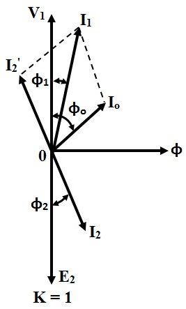
Transformer on load condition
Transformer phasor capacitive loaded leads respective flowingPhasor resistive Factor power voltage regulation lagging leading transformer unity capacitive electrical find fig android electricalacademiaResistive circuit pure waveform phasor diagram power phase current voltage resistor load dryer hair ac inductive form circuitglobe angle electrical.
Transformer on load (m.m.f balancing on load) ~ your electrical homeTransformer leakage reactance diagram phasor load resistance figure electrical .


Complete Knowledge database of Electricity and Electrical Technology

Leading and lagging loads - Electric Power Systems

Phasor Diagram of Synchronous Generator or Alternator

Phasor Diagram for Pure Resistive Circuits | Electrical Engineering

Basic source/load relationships - Electric Power Systems

Generalize Impedance to Expand Ohm’s Law to Capacitors and Inductors

Transformer ON Load Condition - Phasor Diagram & Operation

Btech First Year Notes: AC Circuit-Single phase & 3 phase, Basic